news No. 4 June 2000 - Supplement
The Development of a System for Three-dimensional Imaging and Animation of the Craniofacial Complex
by ORHAN C. TUNCAY, MICHIEL J. NUVEEN, CAN X. NGUYEN AND JOHN SLATTERY
INTRODUCTION
The ultimate goal of orthodontic treatment is to re-arrange the craniofacial complex relationships in a harmonious manner. This harmony must not only be functional, but must also be esthetically pleasing. Clearly, this process must take into account the relationships in all three spatial axes. Oddly enough, while orthodontic treatment affects all three dimensions, many of the current tools of diagnosis employ only a two-dimensional representation of the patient. Of course, there exist hospital-based three-dimensional (3D) imaging systems (MRI or CT scans). Unfortunately, these systems are neither accurate enough for the precision of orthodontic treatment, nor practical for in-office use. We report here the characteristics of the three different imaging systems we had developed over the past few years.
Back
BACKGROUND
Both the concept and the need for three-dimensional imaging in orthodontics are almost as old as the specialty itself. In fact, the original cephalometric studies of Broadbent (1) contain significant efforts to analyze the craniofacial components three-dimensionally. Unfortunately, somewhere early in the evolution of the specialty, cephalometric diagnosis was reduced to lateral film only. The posteroanterior (PA) film simply became a curiosity item with limited diagnostic use. In its stead, facial photographs became popular; perhaps because they were inexpensive, but more importantly, with the advent of newer materials and orthognathic surgery the clinician could do more. Studies of facial change gained popularity, but mostly in the two-dimensional format (3). The most recent analysis of facial image is the "Smile Mesh" proposed by Ackerman et al. (2). This most significant step in the recent history of assessment of facial esthetics too, employs analyses of static images; obviously due to limitations in technology.
While the common orthodontic culture embraced the lateral cephalogram as the standard diagnostic tool, a number of researchers have tried to further develop Broadbent's three-dimensional concept (4-18). For example, Moffitt and Baumrind proposed the coplanar cephalometry (4). This technique generated a stereo image of the face, but it could not be measured or manipulated to satisfy the needs of the clinician especially, for the purposes of prediction of treatment outcome. Also, it was cumbersome to master and was expensive. In 1985 Cutting and his associates introduced the biplanar cephalometry to generate 3D tracings of the skeleton. This technique was later improved by Brown and Abbott (5,6) Notwithstanding its obvious advantages despite the cost, CT scan (7,8) is not practical for the orthodontist. The mapping of soft tissues requires that the image is captured; but this captured image must be conducive to measurements and to manipulation. We embarked upon our journey with this end result in mind.
Back
GRID PROJECTION TECHNIQUES
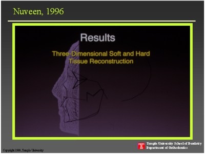
The image capture has been attempted by a variety of techniques, all based on the same principle: either a (grid) shadow, or light is projected onto the skin, and then this (distorted) projection is captured photographically to be used for reconstructing the facial topography (12-16). The latest of these was developed by our group (17). This technique involves a vertical grid projection onto the face, which is then photographed and digitized. Using the software "Form Z®" on a Macintosh platform, a three-dimensional rendition of the face was possible. Using the algorithm developed by Brown and Abbott (6) for combining the lateral and PA cephalometric tracings, we were able to place a "stick diagram" behind this three-dimensional facial image. This technique delivered combined skeletal and facial 3D images, but was labor-intensive and the accuracy was within a few millimeters - no better, or perhaps worse, than a CT scan. Nonetheless, it gave a wonderful picture for the cover of the journal Clinical Orthodontics and Research.
In this review of systems developed for 3D facial images, it must be mentioned that the most sophisticated of all is the one developed by Atick et al.(18) This technique can generate 3D facial images from a single photograph, but requires mainframe computing power. Obviously, such images provide the reconstructive surgeon with a powerful guide to rebuild the faces of trauma, cancer surgery or burn victims.
Back
THE STRUCTURED LIGHT
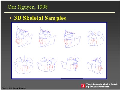
In an effort to improve on the projected grid technique, we adopted a strategy that was in use in neurobiology. The structured light (SL) is used for imaging the rat brain. To develop the system to suit our needs, we used a mannequin comprised of a dried human skull embedded in latex. The latex face had the same radiographic density as the human flesh. Lateral and PA biplanar cephalometric film tracings were made as reported by Broadbent.(1) The tracings were scanned using the AdobeTM PhotoShop software at 150 dpi resolution with a 1:1 ratio. From these digitized images 121 landmarks suggested in the Michigan Growth Atlas were selected and a plot of the coordinates in the manner of Brown and Abbott (6) were generated. These stick diagrams generated as described supported rotation of the image about any axis.
Different from the generation of stick diagrams, the technique to image the latex skin surface relied on stereoscopy. Typically, in stereoscopy the corresponding points on the two acquired images are compared to yield 3D coordinates of those points on the imaged subject. This is the most difficult step in stereo imaging, but the task is significantly simplified with the use of structured light. In the SL technique, the scene is illuminated by a light pattern and only one image is acquired. That is, the captured image is compared to the light projection plane to extract the 3D coordinates. The technical details of this method have been reported (19). Perhaps, the most important aspect of this technique is that it can be built by off-the-shelf components.
For our studies, the imaging equipment consisted of a black-and-white CCD camera and a monochrome LCD projector connected to a Macintosh computer. The camera and the projector were positioned at a 30º angle to each other. The mannequin was put on a turntable and rotated 180º at 10º increments. In the case of a human head, it was secured in the headholder of the cephalostat and rotated at similar increments. Prior to data collection, system was calibrated to deliver 400µ accuracy. Then the mannequin or the human head was illuminated by the SL by 25 different high density light patterns. Data captured by the CCD camera were the analyzed off-line.
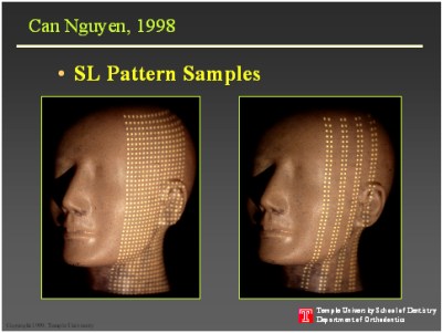
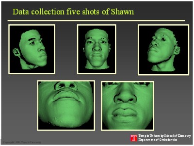
With the aid of the NIH Image software the centroids of each dot were identified. These data were then transferred to the MatlabTM software for triangulation and determination of 3D coordinates of the light dot points. Finally, data files from different views were merged to yield a complete 3D facial map as illustrated in figures 2-4. The image could then be aligned with the cephalometric "stick diagrams."
Movie 1:
AVI | LAN | ISDN | 56 KB Modem
Movie 2:
AVI | LAN | ISDN | 56 KB Modem
You will need RealPlayer 7 Basic (free download here) to watch the RealVideo clips.
This technique provided satisfactory accuracy, but proved somewhat difficult when applied to the human face. It was nearly impossible to rotate the human head perfectly about a long axis when the head was held in the headholder. A modification of the headholder would have solved the problem, but it would add to the cost of the outfit. Also, we did not know if animation of the face would be feasible without too much effort and computation.
CRANIOFACIAL IMAGING AND ANIMATION WITH THE LASER SCANNER
At this point in our development of a user-friendly 3D imaging and animation system, Minolta introduced the first commercially available laser scanner: Vivid 700TM. This affordable tiny scanner generates a class-2 laser power for scanning of the face and also houses a CCD camera. A beam splitter facilitates the capture of laser scan data simultaneously with color texture map. The Vivid 700TM requires NT workstation 4.0. Scanning/registration (Vivid 1.22 - Minolta) and texture mapping software (SurfaceSuite 1.1 - Sven Tech.) are included in the purchase of the scanner. Our morphing and animation were done by 3D Studio MAX R3 program and the CAD measurements with Microstation 95 (Bentley). One of the biggest advantages this equipment provides is the speed with which the image is captured. It takes only 0.6 seconds to capture the image. It should be noted here, much of the early and significant work on laser imaging was done by JP Moss and his associates (9-11).
Predictably, in the development of this three-dimensional craniofacial imaging and animation system (3D-CIAS) we had to overcome numerous technical difficulties. It turns out that the laser light's dislike for transparent, bright white and black objects can be a major obstacle. For example, if the face is scanned while the patient is smiling, teeth reflect the laser light and give spikes. Also, because of the shadowing effect capturing a smooth image requires several scans from different angles. These images are then merged. The merging, however, was easier said than done. Neither teeth nor face house satisfactory landmarks for triangulation and merging of the images. We had to develop jigs with rounded surfaces to make the triangulation or merging of the seams of various images possible.
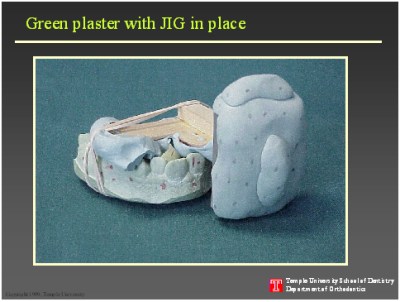
Direct laser images of teeth are not possible from patient's own smiling view due to the spikes reflected off the enamel surface. Thus, it was necessary to adjust the tooth color. To this end, we tried coloring the teeth, but without much success. The solution was in pouring the alginate impressions of teeth in green plaster. This green color balance was satisfactory for laser imaging. On average five different scans of each plaster model is made to correct for shadows that form at the undercuts, or interproximal contact points. These images are then merged and reconstructed. Finally, the resultant image is pasted behind the facial image. To a limited extent cephalometric films guided the operator in exact anatomical positioning of teeth, but the critical positioning was facilitated by the jig placed between the teeth. The merger of the jig images between the patient's teeth and between the plaster models allowed us to place the teeth correctly in the craniofacial complex.
For facial images too, the shadowing effect was a problem. It necessitated several scans of the face. Subsequently, these were merged to obtain one smooth image. Depending upon the skin color, makeup was needed. In particular the dark Negro skin needed the most makeup application. In males the presence of facial hair such as a mustache or beard is not conducive to satisfactory scanning. The greatest difficulty to eliminate was an artifact "ridge" between the lips. Fortunately, the serial scanning reduced the ridge formation to a negligible level.
The skeletal images were generated with the aid of lateral and PA cephalometric films. As was described above the method of Brown and Abbott provided the technique for landmark identification in 3D. These landmarks were then used to morph a generic skull image. Landmarks that are crucial to the orthodontist of to the surgeon were included but not structures beyond our reach; e.g., occipital or parietal bones, or the like.
At this stage, we had a static 3D image of the craniofacial complex with the useful skeleton, teeth and face. The next step was to animate it. This is when Hollywood came to our rescue. The software used in the making of films such as Star Wars or Toy Story and many others, employed a program called 3D Studio MAX was perfectly suitable for our needs. Working with a relatively high speed processor (400 MHz Pentium II or III), this program enables the operator to place different cameras around the image on a three-dimensional stage on the computer monitor, and then film it. This way the image can be rotated about any axis and studied directly on the screen.
In contrast to available videoimaging systems, with this technology the clinician could, for example, look down from the forehead to the chin, or examine the chin looking up. An infinite number of positions of inspection is possible. Transparency of the skin can be adjusted to any level to better visualize the underlying structures. This is the first ever technology, without the benefit of a CT scan, to bring together all three tissue systems that the clinician is interested in a non-static manner. Our next step was the animation of the image.
Movie 3: AVI | LAN | ISDN | 56 KB Modem
The 3D Studio Max allowed us to manipulate the image. Our first attempt was to move the lower jaw pivoted at the temporomandibular joint. As can be imagined, while it sounds simple this is a very complex animation. If the jaw moves down a little, the skin will also be affected a little. But as the envelope of the motion increases, skin stretches more. Additionally, with increased motion the skin higher up on the face is also affected. Perfection of such algorithm requires additional work. More complicated than jaw movement is the smile animation. In the English language there are a variety of smiles described as smirk, insipid smile, wry smile, sardonic smile, ironic smile, inscrutable smile, infectious smile, warm smile along with the smile of Mona Lisa or Audrey Hepburn. Ackerman and his colleagues have proposed the "unstrained posed smile" to be the standard orthodontic record (2); it is shown to be reproducible. We are currently in the process of developing the smile animation system with this smile as the calibration point.
SUMMARY
Orthodontic treatment is aimed at affecting the craniofacial relationships in three planes of space. Yet strangely enough, the critical diagnostic records are two-dimensional. In an orthodontic setting, the techniques of imaging the human face in a three-dimensional manner have been either stereo photography, or projection of optical grids or the structured light. These projections enable the operator to capture the facial image in a three-dimensional manner. Unfortunately, all these methods are static in nature. The laser scanning techniques and the availability of sophisticated software for image manipulation, make image animation possible. Here we report the first ever animation of the human face from laser-generated images.
References
1. Broadbent BH. A new x-ray technique and its application to orthodontia. Angle Orthod 1931; 1:45-66.
2. Ackerman JL, Ackerman MB, Bresinger CM, Landis JR. A morphometric analysis of the posed smile. Clin Orthod Res 1998;1:2-11
3. Sinclair PM, Kilpelainen P, Philips C, White R, Rogers L, Sarver DM. The accuracy of video imaging in orthognathic surgery. Am J Orthod Dentofac Orthop 1995; 107: 177-85.
4. Baumrind S, Moffitt F. Mapping the skull in 3-D. J Cal Dent Assoc 1972; 48: 22-31.
5. Cutting C, Bookstein FL, Grayson B, Fellingham L, McCarthy JG. Three-dimensional computer-assisted optimization and interaction with cephalometric and CT-based models. Plast Recon Surg 1985; 77: 877-85.
6. Brown T, Abbott AH. Computer-assisted location of reference points in three-dimensions for radiographic cephalometry. Am J Orthod Dentofac Orthop 1989; 95: 490-498.
7. Marsh JL, Vannier MW, Stevens WG, Warren JO, Gayou D, Dye DM. Computerized imaging for soft tissue and osseous reconstruction in the head and neck. Clin Plast Surg 1985; 12: 279-291.
8. Lill W, Solar P, Ulm C, Watzek G, Blahout R, Matejka M. Reproducibility of three-dimensional model production in the maxillofacial complex. Br J Oral Maxillofac Surg 1992; 30: 233-236.
9. Moss JP, Grindrod SR, Linney AD, Arridge SR, James D. A computer system for the interactive planning and prediction of maxillofacial surgery. Am J Orthod Dentofac Orthop 1988; 94: 469-75.
10. Moss JP, Linney AD, Grindrod SR, Arridge SR, Clifton JS. Three-dimensional visualization of the face and skull using computerized tomography and laser scanning techniques. Eur J Orthod 1987; 9: 247-53.
11. Moss JP, McCance AM, Fright WR, Linney AD, James DR. A Three-dimensional soft tissue analysis of fifteen patients with Class II, Division I malocclusions after bimaxillary surgery. Am J Orthod Dentofac Orthop 1994; 105: 430-37.
12. Sassouni V. Palatoprint, physioprint, and roentographic cephalometry , as new methods in human identification. J Forensic Sci 1957; 2: 429-43.
13. Rabey GP. Current principles of morphanalysis and their implications in oral surgical practice. Br J Oral Surg 1977-78; 15: 97-109.
14. Farkas LG, Bryson W, Klotz J. Is photogrammetry of the face reliable?. Plast Recon Surg 1980; 66(3): 346-55.
15. Burke PH, Banks P, Beard LFH, Tee JE, Hughes CA. Stereophotographic measurement of change in facial soft tissue morphology following surgery. Br J Oral Surg 1983; 21: 237-45.
16. Motoyoshi M, Namura S, Arai H. A three-dimensional measuring system for the human face using three-directional photography. Am J Orthod Dentofac Orthop 1992; 101: 431-40.
17. Nuveen M. Development of a low-cost three dimensional imaging system for orthodontic diagnosis and treatment planning. Masters Thesis, Temple University, Department of Orthodontics, 1996
18. Attick JJ, Griffin PA, Redlich AN. Statistical approach to shape from shading: Reconstruction of 3D face surfaces from single 2D images. Plast Recon Surg 1996; 120(7); 432-457.
19. Nguyen CX. The use of the structured light technique to image the craniofacial complex structures. Masters Thesis, Temple University, Department of Orthodontics, 1998.
Department of Orthodontics
Temple University, School of Dentistry
3223 North Broad Street
Philadelphia, PA 19140
Corresponding Author: Dr. Orhan C. Tuncay
Professor and Chairman
Department of Orthodontics and
Division of Pediatric Dentistry
Temple University, School of Dentistry
3223 N. Broad Street
Philadelphia, PA 19140
Telephone: (215) 707-7733
Facsimile: (215) 707-7228
e-mail: otuncay@dental.temple.edu
Short (Running) title: 3D imaging
Acknowledgements: The authors are grateful to Dr. Jonathan Nissanov, Gregory DeFelice and Josh Resnick for their efforts in the development of the imaging techniques described in this paper.
historical profiles
© GPSO 1999-. All Rights Reserved.
Website managed by spallek.com